Место расположения
Улица Балдонес 15, Огре, Латвия
The purpose of this document is to provide an airplane basic technical specification (type design) with estimated performance for the purpose of applying for an aircraft type-approval pursuant to UL2 2019 [2].
This regulation is a binding technical document of the DW200 aircraft design. Defines the determination, basic characteristics and technical parameters of the airplane.
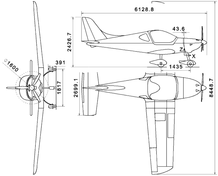
Figure 1.1: Airplane fly.
The DW200 is a two-seat, self-supporting all-metal low-wing aircraft with side-by-side seats. The landing gear consists of a fixed three-wheel landing gear with a controlled nose wheel. The aircraft is fitted as standard with a four-cylinder four-stroke engine Rotax 912 ULS (100HP) and on the ground adjustable three-blade composite propeller.
The fuselage is a half-shell construction - duralumin cover and duralumin reinforcements. The fuselage cross-section is in the central part between the front and rear beam of the wing rectangular with a rounded cabin. Manufacturing is composed of the front lower part, which also includes a wing wing part, from the rear. The rear part of the fuselage has an oval cross section increasing its carrying capacity. The cabin is fitted with organic glass in a composite frame.
Pilot seats are in the center wing area. Seats are made of composite sandwich. There is a luggage compartment behind the seats.
The cabin is heated by ram air from the air exchanger on the exhaust silencer, into the cabin by a pipe distribution system equipped with a shutter and a flap to regulate the amount of warm air into the footwell and the windshield.
The wing is all-metal, rectangular center wing and trapezoidal outer part. It is a single beam construction, consisting of leading, middle and rear ribs, auxiliary rear beam and cover. The main beam is formed by a web, upper and lower flange formed by plates with gradually reduced cross- section over the wing span. The connection of the center wing to the outer wing is double-sheared and is solved by one upper and two lower bolts. The rear auxiliary beam is formed by a web and reinforcing angles that distribute the load from the rear wing hinge. The connection of the rear wing girder to the rear wing girder is realized by one bolt. The wings are finished with composite end arches.
About two-thirds of the wingspan occupy slotted wing flaps, one-third of the aileron. The flaps and wings are all-metal construction with ribs and cover. Two flap hinges are riveted to the rear ribs of the wing. The wings are hung on two hinges. The ailerons are not equipped with a balancing pad.
An integral fuel tank is located between the ribs 2 to 5 in the leading portion of the outer wing. Each tank includes a lockable filler neck, vent, drainage valve, coarse dirt strainer at the tank outlet to the fuel system, and a float for sensing the fuel level in the tank.
The horizontal tail is formed by a stabilizer and a rudder. The stabilizer is a two-beam all-metal shell provided with composite end bends. For installation in the fuselage are two hinges on the front and two on the rear beam. The elevator is continuous. It is attached to the stabilizer by three hinges. The rudder construction is all-metal, consisting of ribs and a cover. Like the stabilizer, the rudder is equipped with composite end bends. The elevator is also equipped with an electrically operated balancing pad that occupies more than a quarter of the span. The plate is all-metal, composed of ribs and cover. Suspension is by piano hinge.
The vertical tail consists of a keel of two-beam construction, which is an integral part of the rear fuselage and all-metal rudder composed of beam, ribs and cover, which is hinged to the keel in two hinges. The end of the keel and rudder is composed of composite arches.
The aircraft has double hand control that controls elevator and ailerons. It is mechanical drawbar. The main element is a body with control levers from which the elevator and gear levers are controlled. All rods have adjustable spherical plain bearings, geared
the levers are fitted with slotted bushings. A common stop of the two control levers for the control of the elevator in the sense of "pulled" and "suppressed" is on the stick body. The aileron control stops are adjustable on the stick body.
The foot control of the rudder is also dual and is rope. Steel cables are suspended between the inner pedals and the eyes of the rudder control pattern located on the keel. The directional control is connected to the nose wheel control via rods. Directional ropes are routed freely.
The flaps are electric. Both right and left flap are controlled by a common torsion bar. At both ends of the torsion bar are adjustable rods that connect the left and right flap on the root rib of the flap.
The deflection of the balancing pads is adjusted by means of buttons located on the pilot's control lever (or elsewhere in the cabin, according to the customer's wish). The position of the balancing pads is indicated by LED indicators located on the dashboard in the pilot's field of vision.
The aircraft has a solid three-wheel landing gear with steerable nose wheel. The main chassis wheels are equipped with hydraulic brakes controlled by the brake lever from the cab.
The front wheel consists of a two-piece rim, two ball bearings and a tire. The wheels of the main undercarriage are attached to the shaft of the laminate leg. The wheels have a split rim, two ball bearings and a brake caliper with a caliper. The brake caliper consists of one hydraulic cylinder with two brake pads. The brake cylinder is connected to the hydraulic cylinder by means of a plastic fluid distribution.
Engine power is controlled by the throttle control lever on the center console between the seats. The lever is connected to the carburetor flap by means of a cable guided in the Bowden.
On the dashboard there is a switch box that serves to start the engine and as a switch of both ignition circuits.
Fuel tanks located in the leading part of the wing have a total capacity of 124 liters. The tanks are riveted from duralumin sheet. It is filled with a throat fitted with a lockable closure. The valve at the lowest point of the tank serves to drain and drain the fuel. The fuel is routed from the tank to the fuel cock, which can switch between the left and right tanks and stop the fuel supply to the engine. From the fuel cock the fuel is led through a fire barrier to a sludge separator fitted with the prescribed fuel screen, from where the fuel is sucked by an electric pump into the carburetors. The relative amount of fuel is measured by an electric fuel gauge with a float in the tank and is indicated by a dashboard indicator.
The electrical installation is single-conductor with grounded negative pole. The mains supply is supplied by a generator with a rectifier and a maintenance-free battery 12V / 14Ah. The onboard network is protected by a main circuit breaker. Individual appliances are switched on by separate switches and protected by separate fuses located on the dashboard.
A separate part of the electrical installation is the double contactless ignition of the engine. By adjusting the ignition key to the appropriate position, each ignition circuit can be switched off independently.
Generator power: 250 W (single phase) Main circuit breaker value: 25 A
The dashboard includes flight instruments, motor instruments, radio communication equipment, electrical equipment and switches, signal lights, ignition switch, fuses, fuel gauge, ventilation and heating control linkage, engine throttle control. It can also be supplemented with other flight instruments and radio navigation equipment according to the user's wishes. Where applicable, instruments, controls and switches are marked with labels explaining their function and direction of movement.
Pilot seats are composite sandwich plates that can be removed if necessary without compromising the stiffness of the fuselage.
The seat belts are four-point as standard. The headphone sockets are located behind the pilot's seats.
The side parts of the cockpit are equipped with composite panels fitted with upholstered armrests with pockets for small aids such as maps.
|
Flight instruments:
|
Engine instruments:
|
|
|
Customized equipment:
|
||
Note: This equipment increases the empty weight of the airplane at the expense of payload.
| Total margins | breal | 8,4487 | m |
| Margin effective | b | 8,26 | m |
| Depth of center wing | cR | 1,4 | m |
| End profile depth | cT | 1,024 | m |
| Wing area | S | 10,385 | m2 |
| Medium geometric chord | cSGT | 1,257 | m |
| Slenderness wings | Ar | 6,57 | - |
| Narrowing the center wing | ηCW | 1 | - |
| Narrowing of the outer wing | ηW | 1,37 | - |
| End profile twist angle (Y=4,13m) | αzkr | -1,91 | ° |
| Center wing deflection angle | ΓCW | 0 | ° |
| Outside wing deflection angle | ΓW | 5,5 | ° |
| Center wing arrow angle (25%) | χCW | 0 | ° |
| Outside wing arrow angle (25%) | χW | 0 | ° |
| Angle of the root profile | φR | +2,0 | ° |
| Depth of center aerodynamic chord of wing | CSAT | 1,2695 | m |
| Position of the main root-end beam | XHI.N | 28,1-29,0 | % |
| Position of the rear root-end beam | XZ.N | 69,2-69,0 | % |
| Flap area | SKL | 0,735 | m2 |
| Flap span | bKL | 1935 | m |
| Flap root depth | cRKL | 414,1 | m |
| Flap depth cSATKL | cSATKL | 380,9 | m |
| Flap end depth | cTKL | 2925 | m |
| Relative damper depth - cSATKL | cSATKL | 29,58 | % |
| Deflection flaps for take-off | δKL | +20 | ° |
| Flap deflection for landing | +40 | ° |
| Span | bKR | 1170,1 | m |
| Depth of aileron - root | cRKR | 324,8 | m |
| Depth cSAT ailerons | cSATKR | 305,5 | m |
| Aileron depth - final | cTKR | 285,4 | m |
| Relative aileron depth - cSATKR | cSATKR | 27,8 | % |
| Aileron area | SKR | 0,357 | m |
| Wind deflection - down | δKR | +22±2 | ° |
| Wing deflection - up | δKR | -15±2 | ° |
| Actual height | bSOPREAL | 1,1410 | m |
| Replacement height | bSOP | 1,1174 | m |
| Depth of root cut | cRSOP | 0,9777 | m |
| Depth SAT | cSATSOP | 0,7367 | m |
| End cut depth | cTSOP | 0,4210 | m |
| SOP area | SSOP | 0,781 | m2 |
| Slenderness SOP (geometric) | ArSOP | 1,60 | - |
| SOP slenderness (effective) | ArSOPEF | 3,86 | - |
| Narrowing the SOP | ηSOP | 2,32 | - |
| Arrow angle to 25% of depth | χSOP | 32,7 | ° |
| The real margin | bVOPREAL | 2,6991 | m |
| Spare span | bVOP | 2,677 | m |
| Depth of root cut | cRVOP | 0,8623 | m |
| Depth of center aerodynamic chord of GTC | cSATVOP | 0,7399 | m |
| End cut depth | cTVOP | 0,6021 | m |
| Area GTC | SVOP | 1,96 | m2 |
| Slenderness of GTC | ArVOP | 3,656 | - |
| Narrowing GTC | ηVOP | 1,43 | |
| Arrow angle to 25% | χVOP | 4,2 | ° |
| Angle of buckling GTC | ΓVOP | 0 | ° |
| Angle setting GTC to ZRT | φVOP | -2 | ° |
| Maximum torso width | bTR | 1,105 | m |
| Maximum torso height | hTR | 1,140 | m |
| Total frontal area of the hull | STR | 1,35 | m2 |
| Gauge | bG | 1,817 | m |
| Wheelbase | LG | 1,435 | m |
| Front flight center | CG | 20 | %cSAT |
| Rear flight center | CG | 35 | %cSAT |
| Empty weight without rescue system | mE | 295 | kg |
| Empty weight with rescue system | mE | 317,5 | kg |
| Minimum pilot weight | mPILmin | 55 | kg |
| Maximum pilot weight | mPILmax | 110 | kg |
| Maximum take-off mass | mmin | 350 | kg |
| Maximum fuel weight (120 liters) | mPAL | 90 | kg |
| Maximum luggage weight | mBAG | 15 | kg |
| Luggage in each wing | mBAG | 20 | kg |
| Maximum take-off weight | mmax | 600 | kg |
| Engine type: | Rotax 912 ULS |
| Engine manufacturer: | Rotax Engines |
| Stroke | 61 mm |
| Drilling | 84 mm |
| A compression ratio | 10,5:1 |
| Total volume | 1352 cm3 |
| Reduction ratio | 2,43 |
| Regime | P [kW] | RPM | MK [Nm] |
| Max. takeoff power | 73,5 | 5800 | 121 |
| Max. continuous power | 69,0 | 5500 | 119,8 |
| Max. krut | 66,0 | 5100 | 128 |
| Manufacturer | E - PROP | |
| Type | On ground adjustable | |
| Diameter | DP[mm] | 1665 |
| Number of pages | iP [-] | 3 |
| Mass | mP [kg] | 3.95 |
| Material | kompozit | |
| Max RPM | 2600 | |
| Direction of rotation (view from pilot) | CCW | |
Power ratings are based on the DW200 under MSA and a maximum take-off weight of 600kg and a Rotax 912ULs engine
| Take-off weight | 600kg |
| Take-off distance up to 15m from asphalt: | 166m |
| Take-off distance up to 15m from grass: | 175m |
| Maximum horizontal speed VH | 225km/h |
| Maximum climb speed VZ/600kg | 5.8 m/s |
| Stall speed on flaps VS0/600kg | 66 km/h |
| Stall speed without flaps VS1/600kg | 73 km/h |
Note: stall speeds will be verified by flight tests.
The airplane is capable of daily ground visibility (VFR) flights. IFR flights and icing operations are prohibited.
The aircraft is not designed for aerobatic operation. Acrobatics and intentional corkscrews are prohibited. The operation for which the airplane is intended includes:
The aircraft is designed to operate with an outside temperature in the range of + 40 ° C to -25 ° C
| Maximum speed limit (90% vD) | vNE | 256 | km/h |
| Maximum operating speed with the flaps fully extended | vFE | 135 | km/h |
| Maximum positive | n1 | +4,0 | - |
| Maximum negative | n4 | -2,0 | - |
Super-leaded petrol according to DIN 516000, Ö-NORM C 1103
EUROSUPER RON 95 unleaded according to DIN 51607, Ö-NORM
1100 BA 95 Natural is recommended for the Czech Republic
AVGAS 100 LL
Any type of engine oil, for example for 4-stroke motorcycle engines, but not aviation oil. Power classification SF, SG according to API.
This document is intended to provide basic technical information about the DW200 and is subject to revision in the event of any change to the data relating to the parameters in this report.